비주얼 스크립트 그래프 유닛 만들기
역자주) 본 내용은 메뉴얼 원본에 있어서 추가하긴 하였으나 사용할 일은 없어 보인다. 매우 전문적인 프로그래머가 어떤 필요에 의해 사용할 일이 있을 수 있지만 프로그래밍이 아닌 비주얼 스크립트 내부의 기능만으로도 상당부분 해결이 되는 문제라고 생각된다. 초보자라면 무시하고 넘어가도록 하자.
비주얼 스크립팅에서 프로그래밍을 한다는 것은 로직 블록을 연결하는 것을 의미한다. 이 블록들을 유닛(Unit)이라고 부른다.
비주얼 스크립팅(Visual Scripting)은 게임(앱) 개발에 필요한 작업들을 처리하도록 세분화된 아주 다양한 형태의 유닛(Units)들을 가지고 있다.
- Events: OnStart, OnUpdate, OnButton과 같은 작업을 실행하는 진입점.
- Flow: 실행이 다른 노드에 의해 트리거되어야(be triggered) 하는 장치(예: if 및 Position 설정)
- Data: 데이터를 갖는 유닛(예: float literal 및 integer literal).
사용자 정의 유닛 만들기
빈 유닛을 새로 만드는 방법:
2. 다음 코드를 스크립트에 복사, 붙여넣기 및 저장한다.
| using Unity.VisualScripting; public class MyNode : Unit { protected override void Definition() //The method to set what our node will be doing. { } } |
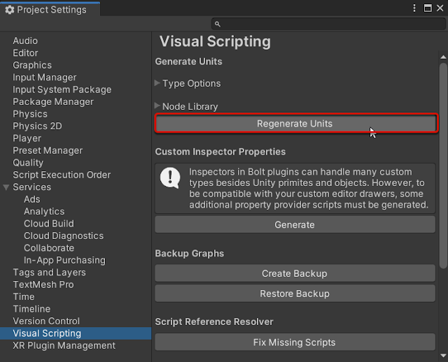
Project Settings 창이 나타난다.
퍼지 탐색기(fuzzy finder)에서 직접 만든 노드를 선택한다. My Node 유닛이 그래프에 표시된다.
 |
| My Node |
참고: 비주얼 스크립팅은 사용자 지정 유닛을 자동으로 처리한다. 노드 라이브러리의 목록에 C# 파일을 추가할 필요는 없다.
포트 추가 및 코드 실행하기
유닛을 생성할 때는 포트를 추가해야 한다.
- 사용자가 처리될 데이터를 추가할 수 있도록 하는 데이터 포트
- 현재의 노드가 작업이 완료된 후 사용자가 해당 노드나 다른 노드를 트리거할 수 있도록하는 제어 포트
유닛에 네 가지 다른 유형의 포트(입력되는 제어 포트와 데이터 포드, 출력되는 제어 포트와 데이터 포트)를 생성하면 된다.
노드 예:
 |
| My Node 사용예 |
포트(Ports):
- ControlInput: 유닛에서 로직을 실행하는 진입점.
- ControlOutput: 현재 포트에 연결된 다음 작업을 트리거(다음 유닛으로 실행 흐름이 넘어감).
- ValueInput: 유닛에 전달되는 모든 종류의 데이터.
- ValueOutput: 유닛 외부에 전달할 모든 종류의 데이터(연결된 다음 유닛으로 데이터가 넘어감).
제어 포트 추가를 추가하는 방법
유닛에 제어 포트를 추가하려면:
- ControlInput 및 ControlOutput 에 원하는 포트 변수를 추가한다.
- 정의 방법(Definition Method)에 있는 포트 변수를 사용한다.
| using Unity.VisualScripting; public class MyNode : Unit { [DoNotSerialize] // No need to serialize ports. public ControlInput inputTrigger; //Adding the ControlInput port variable [DoNotSerialize] // No need to serialize ports. public ControlOutput outputTrigger;//Adding the ControlOutput port variable. protected override void Definition() { //Making the ControlInput port visible, setting its key and running the anonymous action method to pass the flow to the outputTrigger port. inputTrigger = ControlInput("inputTrigger", (flow) => { return outputTrigger; }); //Making the ControlOutput port visible and setting its key. outputTrigger = ControlOutput("outputTrigger"); } } |
이제 다른 제어 포트에 연결할 수 있는 기본적이고 기능을 갖는 플로우 라우팅 유닛(Flow Routing Unit)이 있어야 한다. 플로우 라우팅 유닛(Flow Routing Unit)을 사용하여 그래프에서 흐름의 방향을 변경하여 비정형적이고 유지관리가 어려운 비주얼 소스 코드를 피할 수 있다.
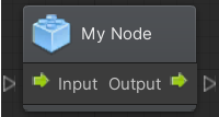 |
| My Node: Input & Output |
값 포트를 추가하는 방법
유닛에 값 포트를 추가하려면 노드에 입력(Input)할 데이터 유형을 정의해야 한다. 두 가지 유형의 데이터가 있다.
- Generic: Object Type(오브제트 타입)으로 코드 상에서 어떤 데이터라도 처리할 수 있도록 한다.
- Type Value: String(문자열), Integer(정수) 및 float과 같은 특정 데이터 타입을 처리하는데 사용된다.
아래의 예시 코드는 문자열 타입의 입력 값 2개를 받을 수 있고, 문자열 타입의 출력 값 1개를 내보낼 수 있는 유닛이 생성된다. 기본값(Default)을 추가할 수도 있다: 아래 예제에서는 myValueA의 기본 문자열 값으로 "Hello"가 설정되어 있다.
| using Unity.VisualScripting; public class MyNode : Unit { [DoNotSerialize] public ControlInput inputTrigger; [DoNotSerialize] public ControlOutput outputTrigger; [DoNotSerialize] // No need to serialize ports public ValueInput myValueA; // Adding the ValueInput variable for myValueA [DoNotSerialize] // No need to serialize ports public ValueInput myValueB; // Adding the ValueInput variable for myValueB [DoNotSerialize] // No need to serialize ports public ValueOutput result; // Adding the ValueOutput variable for result private string resultValue; // Adding the string variable for the processed result value protected override void Definition() { inputTrigger = ControlInput("inputTrigger", (flow) => { return outputTrigger; }); outputTrigger = ControlOutput("outputTrigger"); //Making the myValueA input value port visible, setting the port label name to myValueA and setting its default value to Hello. myValueA = ValueInput<string>("myValueA", "Hello "); //Making the myValueB input value port visible, setting the port label name to myValueB and setting its default value to an empty string. myValueB = ValueInput<string>("myValueB", string.Empty); //Making the result output value port visible, setting the port label name to result and setting its default value to the resultValue variable. result = ValueOutput<string>("result", (flow) => { return resultValue; }); } } |
위의 노드를 연결하려고 하면 흐름이 이 노드를 통과하지만 resultValue 변수의 값이 처리되도록 하는 지시가 없기 때문에 Result Value는 null이다. (다음 단락의 유닛 내부의 로직 실행하기를 참고하라)
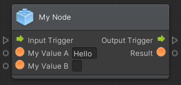 |
| My Node |
유닛 내부의 로직 실행하기
새로 생성된 유닛이 ControlInput name inputTrigger가 트리거될 때 두 개의 문자열을 연결(Concatenate)하여 하나의 문자열로 출력하도록 할 것이다. 이렇게 하려면 ControlInput inputTrigger를 처리하는 람다 식(lambda expression) 내에 로직을 추가하면 된다.
예를 들어, 코드 흐름 내에 다음의 연산(myValueA + myValueB)을 추가한다.
참고: 이 값은 입력 포트에서 나온다.
| flow.GetValue<string>(myValueA) + flow.GetValue<string>(myValueB) + "!!!"; |
전체 코드는 다음과 같아야 한다.
| using System; using Unity.VisualScripting; public class MyNode : Unit { [DoNotSerialize] public ControlInput inputTrigger; [DoNotSerialize] public ControlOutput outputTrigger; [DoNotSerialize] public ValueInput myValueA; [DoNotSerialize] public ValueInput myValueB; [DoNotSerialize] public ValueOutput result; private string resultValue; protected override void Definition() { //The lambda to execute our node action when the inputTrigger port is triggered. inputTrigger = ControlInput("inputTrigger", (flow) => { //Making the resultValue equal to the input value from myValueA concatenating it with myValueB. resultValue = flow.GetValue<string>(myValueA) + flow.GetValue<string>(myValueB) + "!!!"; return outputTrigger; }); outputTrigger = ControlOutput("outputTrigger"); myValueA = ValueInput<string>("myValueA", "Hello "); myValueB = ValueInput<string>("myValueB", String.Empty); result = ValueOutput<string>("result", (flow) => resultValue); } } |
관계(Relation) 추가
관계(relations)란 특정 유닛 내부의 흐름을 보여주는 것이다. 관계를 설정하지 않으면 제어 포트에 유닛을 연결할 때 시각적 문제를 야기할 수 있다. 유닛에 추가할 수 있는 세 가지 유형의 관계는 다음과 같다.
- 할당(Assignment): 데이터가 출력되도록 처리하는 포트를 나타낸다.
- 연속(Succession): 입력 포트에서 출력 포트로 실행되는 경로를 나타낸다. 연속성을 설정하지 않으면 그래프에서 Dim 옵션이 활성화된 경우 연결된 노드가 사라진다. 참고: 실행은 시각적 표현에 관계없이 계속 진행됨.
- 요구(Requirement): 제어 입력 포트를 실행하는 데 필요한 데이터를 나타낸다.
| using System; using Unity.VisualScripting; public class MyNode : Unit { [DoNotSerialize] public ControlInput inputTrigger; [DoNotSerialize] public ControlOutput outputTrigger; [DoNotSerialize] public ValueInput myValueA; [DoNotSerialize] public ValueInput myValueB; [DoNotSerialize] public ValueOutput result; private string resultValue; protected override void Definition() { inputTrigger = ControlInput("inputTrigger", (flow) => { resultValue = flow.GetValue<string>(myValueA) + flow.GetValue<string>(myValueB) + "!!!"; return outputTrigger; }); outputTrigger = ControlOutput("outputTrigger"); myValueA = ValueInput<string>("myValueA", "Hello "); myValueB = ValueInput<string>("myValueB", String.Empty); result = ValueOutput<string>("result", (flow) => resultValue); Requirement(myValueA, inputTrigger); //To display that we need the myValueA value to be set to let the unit process Requirement(myValueB, inputTrigger); //To display that we need the myValueB value to be set to let the unit process Succession(inputTrigger, outputTrigger); //To display that the input trigger port input will exits at the output trigger port exit. Not setting your succession also grays out the connected nodes but the execution is still done. Assignment(inputTrigger,result);//To display the data that is written when the inputTrigger is triggered to the result string output. } } |
참고: 관계 설정 전후
 |
| Relation Setting |
참고: 사용자 지정(custom) 노드의 최종 결과.
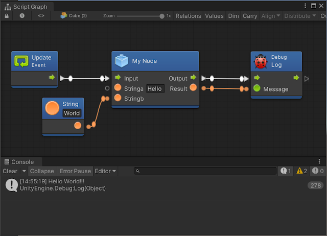 |
| Custom Node |
유닛에 설명(documentation) 추가하기
유닛에 설명을 추가하는 것은 반드시 필요한 사항은 아니지만 사용자가 유닛의 목적을 이해하는데 도움이 된다.
퍼지 파인더나 그래프 인스펙터에서 읽을 수 있는 포트에 대한 요약을 추가하려면 현재 유니티에 새로운 C# 스크립트 파일을 만들고 Editor 폴더에 넣어야 한다. MyNodeDescriptor라는 새로운 C# 스크립트를 만들고 다음 코드를 복사하여 붙여 넣기 한다.
| using Unity.VisualScripting; [Descriptor(typeof(MyNode))] public class MyNodeDescriptor : UnitDescriptor { public MyNodeDescriptor(MyNode unit) : base(unit) {} protected override void DefinedPort(IUnitPort port, UnitPortDescription description) { base.DefinedPort(port, description); switch (port.key) { case "inputTrigger": description.summary = "Trigger the concatenation of the myValueA with the myValueB and return the result string on the Result port."; break; case "myValueA": description.summary = "First string value for the returned result of myValueA + myValueB."; break; case "myValueB": description.summary = "Second string value for the returned result of myValueA + myValueB."; break; case "outputTrigger": description.summary = "Execute the next action after myValueA and myValueB concatenation."; break; case "result": description.summary = "The result string obtained from myValueA and myValueB concatenation."; break; } } } |
그래프에서 유닛을 선택하면 Graph Inspector의 유닛 포트에 대한 설명이 나타난다.
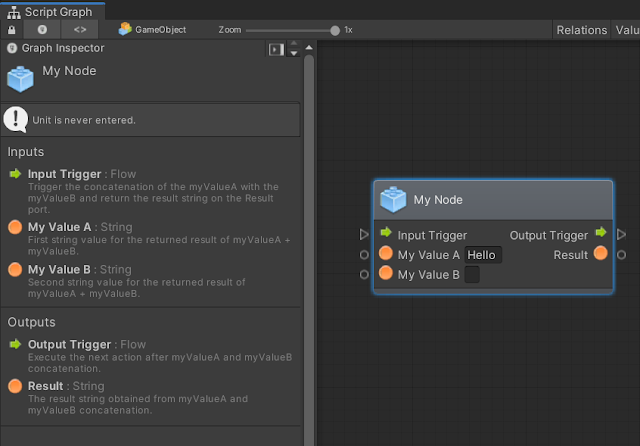 |
| Unit Description |
유닛 커스터마이징하기
유닛 커스터마이제이션(customization, 사용자 지정)은 사용자가 그래프에서 무슨 일이 일어나고 있는지 이해하는 데 도움이 되도록 하는 것이다. 유닛을 사용자 정의하려면 유닛에 속성(attributes)을 설정해야 한다. 다음은 유닛의 모양을 수정하는 데 사용하는 속성 목록이다.
유닛 클래스 속성들(unit class attributes)
속성(attributes)은 노드를 사용자 지정하는 데 사용되며 유닛 앞쪽에 놓여져야 한다.
속성: [UnitTitle("YourTitle")]
 |
| Your Title |
설명: 클래스 이름이 아닌 다른 명칭을 사용하여 유닛 타이틀을 표시한다.
속성: [UnitShortTitle("YourShortTitle")]
 |
| Your Short Title |
설명: UnitShortTitle이 노드에 표시되고 유닛 타이틀이 그래프 뷰에서 숨겨진다.
속성: [UnitSubtitle("Your Subtitle")]
 |
| Your Subtitle |
설명: 현재 유닛 타이틀의 하단에 부재가 작성된다.
속성: [UnitCategory("FirstLevel\")Second Level")]
 |
| Unit Category |
설명: 퍼지 파인더(fuzzy finder)에서 노드를 찾기 위한 가상 경로가 생성된다.
참고: 이를 위해서는 퍼지 파인더를 업데이트해야한다. 파인더에서 노드의 위치가 변경 된다.
속성: [TypeIcon(Typeof(GameObject))]
 |
| Type Icon |
설명: Visual Scripting 아이콘 라이브러리에서 아이콘을 가져오며, 이 아이콘은 unity 내부 라이브러리에 저장되어져 있다.
참고: 사용자가 이 아이콘을 변경할 수는 없다.
포트 속성(Ports Attributes)
포트 속성들은 유닛 클래스 내부의 ControlInput, ControlOutput, ValueInput 및 ValueOutput 변수를 초기화하는 위치보다 앞쪽에 놓여야 한다.
| public class MyNode : Unit { [DoNotSerialize] // Mandatory attribute, to make sure we don’t serialize data that should never be. [PortLabelHidden] // Hiding the port label because we normally hide the label for default Input and Output triggers. public ControlInput inputTrigger; |
속성: [DoNotSerialize]
설명: 모든 포트에 대한 필수 속성 포트. 직렬화되지 않은 데이터가 직렬화되지 않도록 필요한 경우.
속성: [PortLabelHidden]
 |
| Port Label Hidden |
설명: 포트 아이콘 옆에 있는 텍스트 레이블 숨기기
참고: 레이블이 숨겨져 있지 않으면 포트 변수가 Definition: method의 키와 동일하게 만들어 진다.
예를 들면 다음과 같다.
| myValueA = ValueInput<string>("myValueA", "Hello "); |
<원문>

댓글
댓글 쓰기